After I installed my Jim Wolf Technologies POP-Charger air intake, my car would stall at highway speed whenever I pushed in the clutch and took my foot off the gas. Unacceptable, to say the least. There is a FAQ on TT.net on how to fix this problem by placing tape on the filter to create the right kind of "turbulence" so that the Mass Airflow Sensor (MAS), just downstream from the air filter, can get a better reading. I thought buying a high-flow air filter and then blocking some of it with tape sounded a bit counterproductive, although it reportedly fixed the stalling problem.
"POP-Charger" is proprietary jargon that Jim Wolf uses when selling his particular brand of cone intake filter. "POP" stands for "Performance Optimized Program," which is kinda weird. I think that acronym is a throwback to the day when JWT used to sell a "400 HP kit" for our cars, which included intake, exhaust and ECU chip, so the intake was part of the total "Program." Or the intake was "Programmed" to the ECU, I dunno. So all JWT POP-Chargers are cone filter intakes, but not all cone filter intakes are POP-Chargers.
Most folks will tell you that the JWT "POP-Charger" cone filter intake is the best of its kind for workmanship, fit, and quality of the filter material. The mounting bracket is CNC machined. This filter is reusable, after it is cleaned and oiled. Also, the JWT POP-Charger is also the only cone filter I know of that is California smog legal. I’ve been told but have not confirmed that S&B makes the filter material for Jim Wolf.
So I examined the intake system, and thought, "Where would I go if I were an air molecule getting sucked into a great car like the Nissan 300ZX Twin Turbo at speed?" I then paid a little homage to Bernoulli, and moved my air filter a few inches. This completely eliminated my stalling problem.
First of all, there are two important plastic pieces that should be present for things to work right, and for the filter to be adequately protected at the same time. These are the splash shield through which you poke a hole to attach the front of the air filter, and the undertray which also helps to direct air coming through the front fascia and into this compartment.
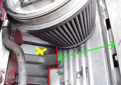 The plastic undertray is marked with the yellow X. The depth of the splash shield is shown by the green arrow. The bottom edge of the splash shield is outlined in red. The plastic undertray is marked with the yellow X. The depth of the splash shield is shown by the green arrow. The bottom edge of the splash shield is outlined in red.
The undertray and splash shield are not attached. There is space between them for air to enter from through the front fascia.
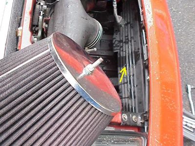
With the air filter removed from the car, the bolt on its chrome cap is plainly visible. The point of this "hole" write-up is to show where to poke the hole through the splash shield for this cap bolt. I marked the hole I made with a yellow arrow in the background of the pic. Counting the ridges on the splashshield helps place the hole without much trial and error. Looks like the hole is between the third and fourth ridges, to me.
The yellow X's are on the undertray and the red outlines the bottom, lower edge of the splash shield. The yellow arrows point to the clamps that might have to be loosened in order to rotate the entire rubber intake T piece down so that the air filter can be mounted low enough on the splash shield. The idea is to get the air filter as low as possible but still behind and protected by the splash shield.
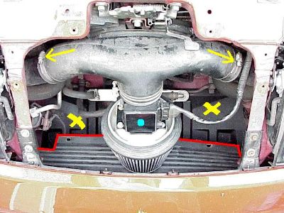
The blue dot is on the Mass Airflow Sensor (MAS). Proper placement of the air filter on the splash shield ensures the MAS can send accurate measurements of airflow to the car's central Electronic Control Unit (ECU).
If the airflow reaching the MAS is impeded by the splash shield, then the signal sent to the ECU by the MAS does not accurately reflect the car speed and engine conditions. The ECU then sends a signal to the fuel injectors that causes the car to run too rich, which in turn causes the engine to stall.
If one could look through the front fascia and the splash guard, the front metal cap of the air filter would be lined up with the lower edge of the splash shield like this:
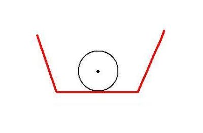 This is the correct way, front view. This is what I meant when I described this spatial arrangement as a "circle sitting on a line." This diagram is a much better way to get the point across. This is the correct way, front view. This is what I meant when I described this spatial arrangement as a "circle sitting on a line." This diagram is a much better way to get the point across.
From the side, the correct way to install the splash shield would look like this. The front of the car would be to the left side of the schematic. Notice the bottom, front edge of the air filter is even with the bottom, lowest edge of the splash shield. Air flow is shown by the green arrows. Enough air can get through the filter and be metered by the MAS because the filter is not placed too far up and hidden behind the splash shield.
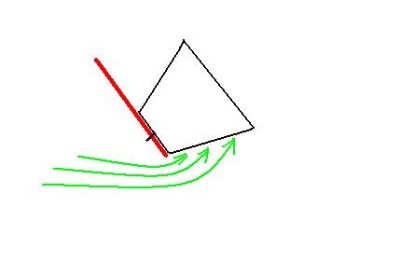 This is the correct way, side view. This is the correct way, side view.
When the filter is placed even a few inches further up the splash shield, there is too much dead space around the filter and air flow has a harder time reaching the mass airflow sensor.
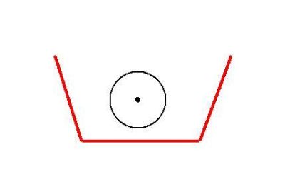 This is the wrong way, front view. This is the wrong way, front view.
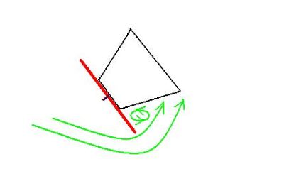 This is the wrong way, side view. Not enough air can reach the Mass Airflow Sensor. There is too much turbulence and possibly even negative pressure around the air filter. This is the wrong way, side view. Not enough air can reach the Mass Airflow Sensor. There is too much turbulence and possibly even negative pressure around the air filter.
Before I moved my air filter down the splash shield a bit, my car would stall every time at highway speed, with the clutch in and my foot off the gas. After I relocated the filter in this fashion, it has not happened once. I cannot induce the stall even when I try. That is good.
I have not experimented with mounting the air filter even lower on the splash shield, which could be tried, I suppose. But it works well the way it is now, and I don't want the filter hanging too low which could unecessarily expose the intake to dirt, water and puddles.
| 