We are currently creating content for this section. The jury is still out on this mod as to whether or not it really helps. Until this mod is tested on a dyno the results are unproven.
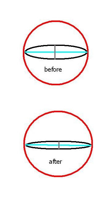
 This is a schematic drawing, not to scale, looking down the barrel of either one of the two throttle bodies with the intake hose removed. Both pics represent wide open throttle (WOT). The two diagrams represent before and after the mod described below. The idea is to present a smaller surface area of the butterfly flange to the rush of incoming air at WOT, which presumably will allow for better flow. The red circle is the cross sectional area of the TB. The black line is the outer edge of the butterfly flange. This is a schematic drawing, not to scale, looking down the barrel of either one of the two throttle bodies with the intake hose removed. Both pics represent wide open throttle (WOT). The two diagrams represent before and after the mod described below. The idea is to present a smaller surface area of the butterfly flange to the rush of incoming air at WOT, which presumably will allow for better flow. The red circle is the cross sectional area of the TB. The black line is the outer edge of the butterfly flange.
The blue line represents both the diameter of the TB and the "long axis" of the ellipse that is the butterfly flange at WOT. The short vertical grey line is the short axis of the ellipse, and is the only variable in our equations.
When the round butterfly flange is opened or tilted, the shape of its surface presented to the incoming atmospheric air changes from a circle to an an ellipse. At WOT, the "flattest" possible ellipse should be presented to the incoming air for maximum flow.
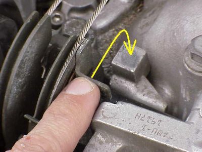
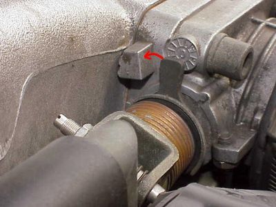
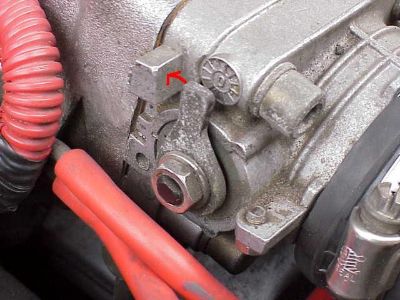
By bending the metal tab in the pic out of the way, the butterfly flanges open further, decreasing the length of the short axis of the ellipse.

Surface area (SA) of a circle, in this case, our TB's without the butterfly, = Pi (r)squared
SA of the ellipse formed by the open butterfly flanges = Pi x (long axis x short axis)
At WOT, TB SA = (TB opening surface area) – (butterfly flange surface area).
If we designate x to be the TB SA after the mod, and y the TB SA before the mod, then x - y = z, with z being the additional SA gained for air flow in one throttle body after the mod. z/y X 100 = percent SA gained after the mod.
The difference is significant. This difference is even more striking if one realizes that flow does not have a linear relationship to the size of the pipe. Poiseuille's equation states that flow through a pipe is inversely related to the FOURTH power of the radius. Therefore, small decreases in the radius of the blocking butterfly flange should lead to proportionately much larger increases in flow. All measurements are for one throttle body only.


The Throttle Position Sensor (TPS) located on the side of the throttle bodies. I have heard of more than on person who only got his TPS to calibrate within spec after this mod. There is also a possibility that this mod increases the voltage from the TPS to the ECU at WOT, which leads to a performance gain.
Assumptions and potential errors for doing this mod include:
1) These are all theories that have not been tested or backed up in the lab or on a dyno. There is a rumor that Paul at Avalon Racing once showed a gain in horsepower with this mod.
2) Measurements of the butterfly flange were "eyeball" estimations, but the numbers were kept conservative in order to reduce any false positive benefit.
3) The throttle bodies are mounted at a slight downward angle to the intake plenum. This means that opening up the butterfly valve all the way as suggested above may not in fact be presenting the lowest possible surface area to the flow of incoming air.
4) Poiseuille’s equation was originally described for laminar liquid flow, then later applied to turbulent liquid flow. This example deals with turbulent gas flow which is somewhat of a stretch, but acceptable IMHO.
5) This still begs the question as to why the Nissan engineers would not design the butterfly flanges to fully open from the factory.
6) The effect on the TPS voltage also needs to be documented but is another possible source of a gain in performance from this mod.
| 

